About Mapping Parameters and File Parameters | ||
| ||
By default, the Design Gateway automatically creates mappings between parameters and file parameters with the same name within a given simulation process flow if certain attributes match (e.g., type, structure, input-output relationship). You can control this behavior by selecting the Auto map matching parameters preference option. For more information, see Setting Gateway Preferences.
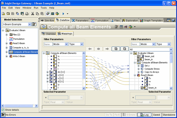
The following example shows an example of mappings in a model:

Explicit mappings are shown with a solid line. Implicit mappings are shown by a dotted line. Lines with a single arrow show a unidirectional mapping from one parameter to another parameter in one direction. Lines with two arrows show a bidirectional mapping—a combination of two unidirectional mappings from parameters in opposite directions.
For convenience, you can work with parameter and file parameters from the Mappings subtab. You can add parameters and aggregate members as described in Adding New Parameters. Similarly, you can add file parameters as described in Adding File Parameters. You can also delete parameters and file parameters as described in Deleting Parameters and File Parameters. In addition, you can edit parameters and file parameter attributes as described in Editing Parameters and Editing File Parameters.