From the Design Gateway,
select the model that you want to configure.
Drag any component into the area below a process
component.
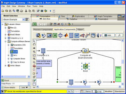
In the following example, an Excel component has been added to the model
under the Compute all Beam Elements Loop component  .
.

Click the Sim-flow Link  button.
Click the Start icon  to the left of the process component’s subflow.
In the above example you would click the Start
icon  to the left of the Compute all Beam Elements
Loop component’s subflow.
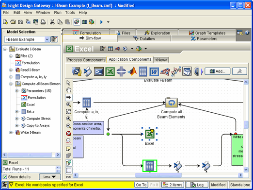
Drag the mouse pointer to the newly added component, and release the
mouse button.
In this example you would move the mouse pointer to the Excel component,
and release the mouse button.
Isight
creates a partial parallel simulation process flow as shown in the following
example.

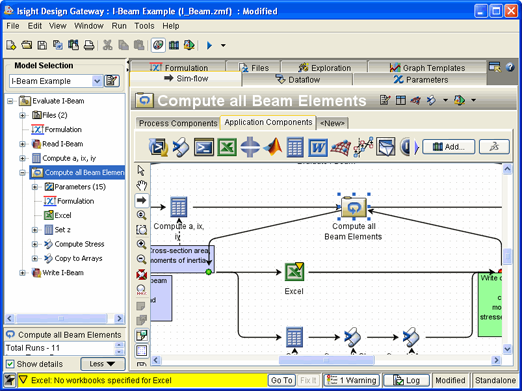
Click the newly added component, drag the mouse pointer to the Stop
icon  to the right of the process component’s subflow, and
release the mouse button.
In this example you would drag the mouse pointer to the Stop icon  to the right of the two Script components
  .
.
Isight
creates the parallel simulation process flow as shown in the following
example.

If desired, add additional components to the parallel simulation process
flow by dragging and dropping the components on the simulation process
flow arrows on either side of the newly added parallel simulation process
flow.
You can remove simulation process flow arrows from the Sim-flow
tab canvas by right-clicking the arrow that you want to delete, and selecting
Delete.
If desired, save the model.