Mapping Parameters | ||
| ||
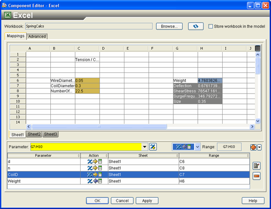
Click in the cell that contains the value 0.3 (which is to the right of the cell that is labeled Coil Diameter).
By clicking in this cell, the value of the cell (C7) is added to the Parameter text box and is highlighted in yellow.
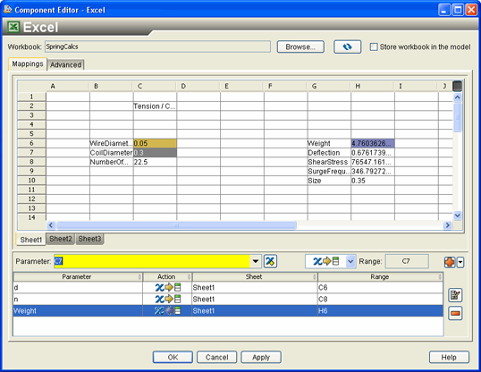
Click the
 button to add the parameter to the list
at the bottom of the editor.
button to add the parameter to the list
at the bottom of the editor.
The cell (C7) is highlighted in gold as an input parameter, just like the previous two input parameters.
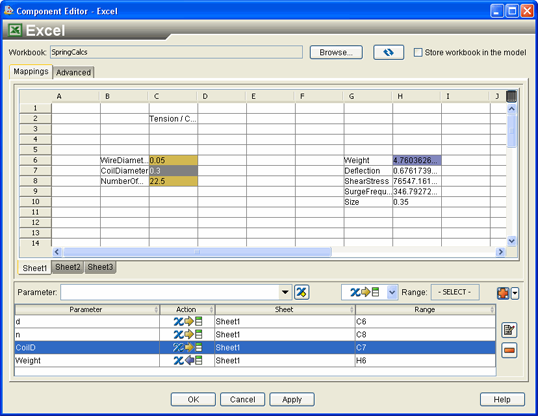
Some of the cells contain text that describes the values in the adjacent cells.You can use the name-value mapping option to use this text instead of typing the parameter name. You will now use name-value mapping to map the remaining parameters in the workbook.
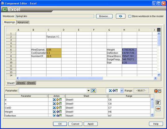
Click and drag in the workbook to highlight cells G7 through H10. Do not highlight cells G6 or H6; because this parameter is already defined.
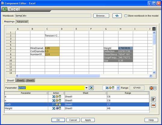
From the
 list, select
  .
.
This action changes the mapping direction from input to output.
Click the
 button next to the button, and select Add Name-Value
mapping.
button next to the button, and select Add Name-Value
mapping.
All the selected output parameters are added to the list at the bottom of the editor.
Click OK.
Your changes are saved, and the component editor is closed. You are returned to the Design Gateway.