3DNLG-7: Elastic large deflection response of a hinged spherical shell under pressure loading | ||
| ||
ProductsAbaqus/Standard
Elements tested
- CSS8
- S3
- S3R
- S4
- S4R
- S4R5
- S8R
- S8R5
- S9R5
- STRI3
- STRI65
- SC6R
- SC8R

Problem description
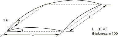
Model:
The shell midsurface is defined in terms of global Cartesian coordinates, where
Material:
Young's modulus = 69, Poisson's ratio = 0.3.
Boundary conditions:
Simply supported along all edges ().
Loading:
Evenly distributed follower pressure load normal to shell surface. = 0.1.
Reference solution
This is a test recommended by the National Agency for Finite Element Methods and Standards (U.K.): Test 3DNLG-7 from NAFEMS Publication R0024 “A Review of Benchmark Problems for Geometric Non-linear Behaviour of 3D Beams and Shells (SUMMARY).”
The published results of this problem were obtained with Abaqus. Thus, a comparison of Abaqus and NAFEMS results is not an independent verification of Abaqus. The NAFEMS study includes results from other sources for comparison that may provide a basis for verification of this problem.
Results and discussion
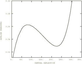
In the following table, limit points 1 and 2 correspond to the peak and local minimum, respectively, of the load-displacement curve. All the meshes share the same nodal spacing.
| Element | Limit point 1 | Limit point 2 | ||
|---|---|---|---|---|
| Pressure | at center | Pressure | at center | |
| S3/S3R | 0.06639 | 78.15 | 0.03300 | 220.9 |
| S4 | 0.06581 | 78.84 | 0.03133 | 223.5 |
| S4R | 0.06581 | 78.98 | 0.03134 | 223.5 |
| S4R5 | 0.06281 | 79.62 | 0.02956 | 224.4 |
| S8R | 0.06263 | 79.14 | 0.02849 | 223.6 |
| S8R5 | 0.06261 | 79.21 | 0.02882 | 223.7 |
| S9R5 | 0.06261 | 79.08 | 0.02883 | 223.4 |
| STRI3 | 0.06397 | 78.61 | 0.03175 | 221.9 |
| STRI65 | 0.06244 | 79.26 | 0.02886 | 224.0 |
| SC6R | 0.06749 | 81.0 | 0.03388 | 217.1 |
| SC8R | 0.06679 | 81.9 | 0.03213 | 217.6 |
| CSS8 | 0.06619 | 83.9 | 0.03278 | 221.1 |
Response predicted by Abaqus
Similar load-displacement curves are obtained for all test cases. The
response predicted using S8R5 elements is shown below.
Input files
- n3g7xf3x.inp
-
S3/S3R elements.
- n3g7xe4x.inp
-
S4 elements.
- n3g7xf4x.inp
-
S4R elements.
- n3g7x54x.inp
-
S4R5 elements.
- n3g7x68x.inp
-
S8R elements.
- n3g7x58x.inp
-
S8R5 elements.
- n3g7x59x.inp
-
S9R5 elements.
- n3g7x63x.inp
-
STRI3 elements.
- n3g7x56x.inp
-
STRI65 elements.
- nlg7_std_sc6r.inp
-
SC6R elements.
- nlg7_std_sc8r.inp
-
SC8R elements.
- nlg7_std_css8.inp
-
CSS8 elements.