Start the Isight
Design Gateway,
and connect to the remote SIMULIA Execution Engine
you used to create your federation environment.
Create a simple model by adding a Calculator
component to a root Task component.
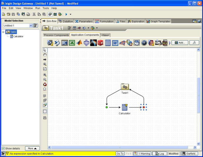
Double-click the Calculator component.
The Calculator Component Editor appears.
Configure the Calculator component by typing the following equations:
AR = (Span**2)/Area
C0 = 2 * pi() * aa
C1 = C0 / (1 + (C0/(pi()*AR)))
Lift = C1 * Area * Density * ((Speed**2)/2)
The aerodynamic calculations have several inputs and outputs. You
will expose only a subset of these to the remote user of this model.
Click Allow exceptional values.
Click OK to close the component editor and to
save your changes.
You are returned to the Design Gateway.
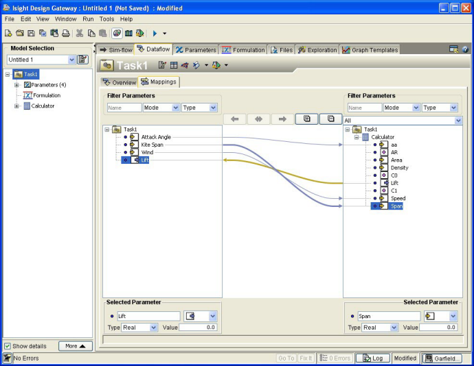
Click the Design Gateway’s Dataflow tab, and
verify that the Mappings subtab is selected.
In the Model Explorer area on the left side of
the Design Gateway, click the Task component.
The Task component’s parameters are displayed on the left side of
the Mappings subtab. The Calculator component’s
parameters are displayed on the right side of the subtab.
Create four new parameters for the Task component.
-
On the left side of the Mappings subtab, right-click
the Task component icon.
-
Select Add Parameter.
The Add Parameter dialog box appears.
-
In the Name text box, enter Attack Angle.
-
Verify that Input is selected from the Mode
list.
-
Click OK.
The new parameter appears below the Task component’s
icon.
-
Repeat Steps a through e, creating the following parameters:
Kite Span (Input parameter)
Wind (Input parameter)
Lift (Output parameter)
Verify that the Lift parameters were mapped automatically.
An arrow should appear in the center of the Mappings
subtab, connecting the two parameters. These parameters were mapped automatically
because they have the same name in both the Task and Calculator components.
Create the appropriate mappings between the remaining Task
component parameters and the existing Calculator
component parameters.
-
On the Mappings subtab, click and drag the Attack
Angle parameter from its position below the Task
component to the Calculator component’s aa
parameter.
-
Once the aa parameter is highlighted, release your
mouse button.
An arrow appears, connecting (mapping) the two parameters.
-
Repeat Steps a and b, mapping the following parameters to each other:
Kite Span to Span
Wind to Speed
Your final mappings should appear as shown below. Only the parameters
that appears on the Task component are exposed to the remote user of
this model, which effectively hides the implementation of the model from
the remote user. Furthermore, although they represent the same parameter
value, the parameter names exposed to the user can vary. For example,
the Calculator component’s aa parameter is displayed
in the Task component as the Attack Angle parameter.
Click the Design Gateway’s Parameters tab.
The Task component’s parameters are listed.
In the Value column, enter values for each of
the Task component’s parameters. You can enter
any value for the parameters.
Publish the model to the remote SIMULIA Execution Engine’s
library and make it available as a service to a user from the local SIMULIA Execution Engine.
-
From the Design Gateway File menu, select Publish.
The Publish dialog box appears.
-
In the Name text box, type the name the model
will use in the SIMULIA Execution Engine
library. For example, kite.
-
In the Path text box, type the directory for
the model. This directory will be created in the library if it does not
already exist. For example, shared.
-
Select Share this model with other SIMULIA Execution Engine environments.
-
In the SIMULIA Execution Engine Name and User(s)
columns, type an asterisk (*).
This step allows any user from any other defined partner SIMULIA Execution Engine
installation access to this model. If desired, you can enter specific
user IDs and SIMULIA Execution Engine
names to restrict access to particular partner installations and/or users
at those installations.
-
If desired, enter a description of the model in the corresponding text
box.
-
Click Publish.
The model is published and is made available as a service in the federated
environment.
If desired, save the file to your local disk using the File
/ Save As option.
Close the Isight
Design Gateway.