Start the Isight
Design Gateway,
and connect to the local SIMULIA Execution Engine
you used to create your federation environment.
Create a simple model by adding a Calculator
component to a root Task component.
This Calculator component is used to calculate the span of the kite
configuration that you want to analyze.
Double-click the Calculator component.
The Calculator Component Editor appears.
Configure the Calculator component by entering the following equation:
span = PartA + PartB
This equation has two input parameters (PartA and PartB)
and one output parameter (span).
Click OK to close the Calculator Component
Editor and to save your changes.
You are returned to the Design Gateway.
Verify that the Reference component is available
on the Design Gateway
Component Palette (on the Sim-flow
tab). If it is not available, add it using the following procedure:
-
On the Design Gateway
Component Palette, click Add.
The Isight Library dialog box appears.
-
On the left side of the Isight Library dialog
box, click SIMULIA Components.
-
In the list of components, click Reference.
-
Click Add to Palette.
-
Click OK to confirm the selection.
-
Click Close to return to the Design Gateway.
The Reference component now appears on the Component
Palette.
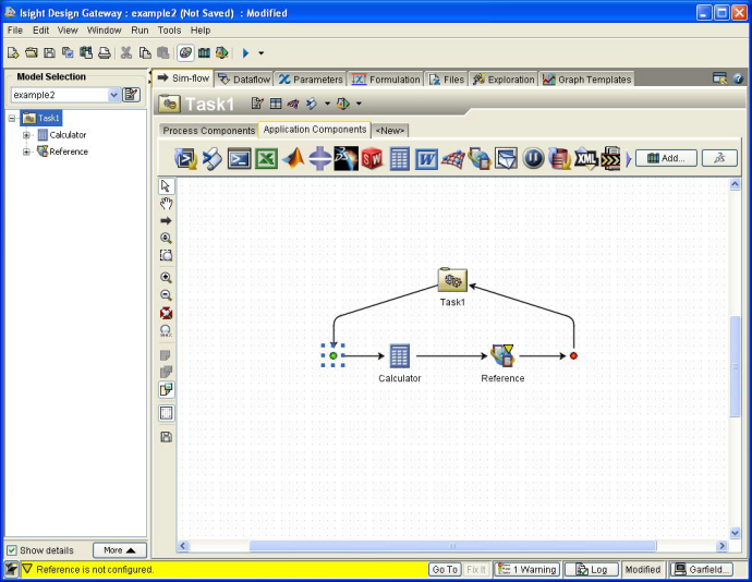
To the right of the existing Calculator component,
add a Reference component to the simulation process flow.
Your Design Gateway should appear as shown below.
Double-click the Reference component in the simulation
process flow.
The Reference Component Editor appears.
Configure the Reference component to use the
aerodynamic service with the local model.
-
Click Choose Model.
The Select Model Reference dialog box appears.
-
On the left side of the dialog box, expand the Remote Partner
option.
The list of all the partner installations that the administrator has
defined appears.
-
Expand the partner that you want to use.
A search is made on the selected remote SIMULIA Execution Engine
for models that are shared and accessible to the user performing the
search. The available models are displayed below the partner name.
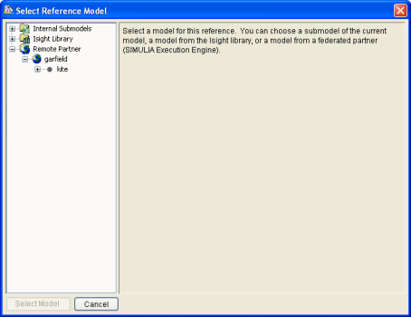
-
Click the model you want to use. In this example, click the kite
model.
Information about the model appears on the right side of the Select
Reference Model dialog box.
-
Click Select Model.
You are returned to the Reference Component Editor,
and it displays the inputs and outputs of the remote service. These remote
input parameters and output parameters are read and used to populate
the input and output parameters of the local Reference component. The
default values for the input parameters were taken from the default values
defined in the remote service. Furthermore, the name of the partner,
along with the remote model name and version are shown above the input/output
list.
-
Click OK.
The Reference Component Editor is closed, and
you are returned to the Design Gateway.
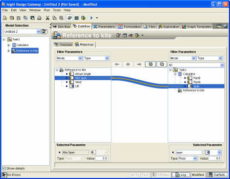
Click the Design Gateway Dataflow tab, and verify
that the Mapping subtab is selected.
In the Model Explorer area on the left side of
the Design Gateway, click the Reference component.
The Reference component’s parameters are displayed on the left side
of the Mappings subtab. All of the model’s parameters
are displayed on the right side.
Create the appropriate mapping connecting the span
output parameter of the Calculator component to
the Kite Span input parameter of the Reference
component.
-
On the Mappings subtab, click and drag the Kite
Span parameter from its position below the Reference
component to the Calculator component’s span
parameter.
-
Once the span parameter is highlighted, release your
mouse button.
An arrow appears, connecting (mapping) the two parameters.
In the Model Explorer area on the left side of
the Design Gateway,
click the Calculator component.
Click the Parameters tab.
The parameters for the Calculator component are displayed.
Set the values for the PartA and PartB
parameters. You can set the values to anything you desire. The sum of
these two values will become the Kite Span value (for
example, 5.0 for PartA and 10.0
for PartB).
Click the  button to execute the model on the local SIMULIA Execution Engine,
just like any other model.
button to execute the model on the local SIMULIA Execution Engine,
just like any other model.
The Runtime Gateway
appears. The Reference component is executed by calling the remote SIMULIA Execution Engine
to run the aerodynamic analysis. The results of the execution are returned
from the remote SIMULIA Execution Engine
and become the outputs of the Reference component in the local model.
Once the execution is complete, click the Runtime Gateway
Parameters tab.
In the Model Explorer area on the left side of
the Runtime Gateway, click the Reference component
to view the final job results.
The Reference component results appear. The remote model was executed
by calling the remote SIMULIA Execution Engine
to run the aerodynamic analysis. The results of that execution were returned
from the remote SIMULIA Execution Engine
and became the outputs of the Reference component in this local model.
Close the Runtime Gateway.
If desired, save the file to your local disk using the Design Gateway’s
File / Save As option.