Shell features | |||||
|
| ||||
To create an extruded shell feature, you sketch a profile and extrude it through a specified distance (d), as shown in Figure 1.
Figure 1. An extruded shell feature.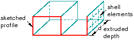
In addition, you can apply either draft or twist to the extrusion, as shown in Figure 2.
Figure 2. An extruded shell feature with draft and one with twist.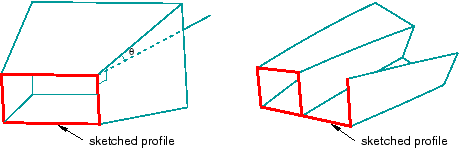
You define the draft angle for an extrusion with draft or the center of twist and the pitch (the extrusion distance in which a 360° twist occurs) for an extrusion with twist. Select from the main menu bar to create this type of feature.
To create a shell loft feature, you transition the shape from the initial loft section to an end section of a different shape or orientation. Abaqus/CAE determines the shape between the start and end sections using tangency constraints, intermediate sections, and a path curve. A simple loft (with only two loft sections, no tangency constraints, and a straight path) is shown in Figure 3. Select from the main menu bar to create this type of feature.
Figure 3. A shell loft feature.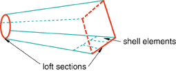
To create a revolved shell feature, you sketch a profile and revolve it through a specified angle (α). A construction line serves as the axis of revolution, as shown in Figure 4.
Figure 4. A revolved shell feature.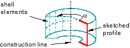
In addition, you can enter a pitch value to translate the profile along the axis of revolution as it is revolved; Figure 5 shows a revolved shell with pitch.
Figure 5. A revolved shell feature with pitch.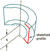
The dimension h represents the translation of the sketched profile due to pitch; h would be equal to the pitch if the part was revolved a full 360°. Select from the main menu bar to create this type of feature.
To create a swept shell feature, you sketch a profile and sweep it along a specified path, as shown in Figure 6.
Figure 6. A swept shell feature.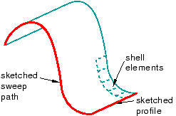
Select from the main menu bar to create this type of feature. For more information, see Defining the sweep path and the sweep profile.
To create a planar shell feature, you sketch the outline of the shell on a selected planar face or datum plane, as shown in Figure 7.
Figure 7. A sketched shell feature.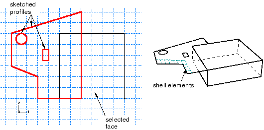
When you sketch on a planar face (for example, the side of a cube), the shell feature is created only where it extends beyond the face; a shell feature cannot overlap a face. A sketch on a planar face of a cube and the resulting shell feature are shown in Figure 7. In this example the shell feature is a fin extending beyond the selected face of the cube. Select from the main menu bar to create this type of feature.
To create a shell-from-solid feature, you convert the faces of a solid feature to shell features; in effect, hollow out a solid. A shell-from-solid feature is shown in Figure 8. Select from the main menu bar to create this type of feature.
Figure 8. A shell-from-solid feature.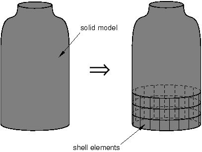
You can use any of the shell tools to add a shell feature to a part that you created in three-dimensional modeling space; however, when you are working on parts created in two-dimensional or axisymmetric modeling space, you can use only the planar shell tool to add a shell feature. You use the Property module to create a section prescribing the desired thickness and to assign the section to the shell feature. For more information, see Defining sections, and Which properties can I assign to a part?.
Many of the figures illustrate how the shell features might later be meshed. You can mesh a shell feature using:
Two-dimensional or axisymmetric continuum elements (limited to planar shell features)
Three-dimensional shell elements
Membrane elements