CARDAN

Connection type CARDAN provides a rotational connection between two nodes where the relative rotation between the nodes is parameterized by Cardan (or Bryant) angles. A Cardan-angle parameterization of finite rotations is also called a 1–2–3 or yaw-pitch-roll parameterization. Connection type CARDAN cannot be used in two-dimensional or axisymmetric analysis.

When connection type CARDAN is used with connector behavior, the relative rotation axis with the highest resistance to rotational motion should be assigned to the second component of relative rotation (component number 5) to avoid “gimbal lock,” a singularity in the rotation parameterization for relative rotation angles β=±π/2.

Related Topics
Connector elements
Connector element library
In Other Guides
*CONNECTOR BEHAVIOR
*CONNECTOR SECTION

ProductsAbaqus/StandardAbaqus/ExplicitAbaqus/CAE

Description
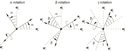
Figure 1. Connection type CARDAN.

The CARDAN connection does not impose kinematic constraints. A CARDAN connection is a finite rotation connection where the local directions at node b are parameterized in terms of Cardan (or Bryant) angles relative to the local directions at node a. Local directions {e1b,e2b,e3b} are positioned relative to {e1a,e2a,e3a} by three successive finite rotations α, β, and γ as follows:

  1. Rotate by α radians about axis e1a;

  2. Rotate by β radians about the intermediate 2-axis, e2=cos⁢α⁢e2a+sin⁢α⁢e3a; and

  3. Rotate by γ radians about axis e3b.

Rotation angle β should be moderate (magnitude less than π/2), whereas α and γ may be arbitrarily large (i.e., magnitude greater than 2⁢π). The Cardan angles are determined by the local directions as

α=-tan-1⁢(e2a⋅e3be3a⋅e3b)+m⁢π;
β=sin-1⁢(e1a⋅e3b),    -π2<β<π2;
γ=-tan-1⁢(e1a⋅e2be1a⋅e1b)+n⁢π.

Here, m and n are integers that account for rotations with a magnitude greater than π.

The three available components of relative motion in the CARDAN connection are the changes in the Cardan angles positioning the local directions at node b relative to the local directions at node a. Therefore,

u⁢r1=α-α0;    u⁢r2=β-β0;    and    u⁢r3=γ-γ0;

where α0, β0, and γ0 are the initial Cardan angles. The connector constitutive rotations are

u⁢r1m⁢a⁢t=α-θ1r⁢e⁢f;    u⁢r2m⁢a⁢t=β-θ2r⁢e⁢f;    and    u⁢r3m⁢a⁢t=γ-θ3r⁢e⁢f.

The kinetic moment in a CARDAN connection is determined from the three component relationships:

mC⁢a⁢r⁢d⁢a⁢n=m1⁢e1a+m2⁢(cos⁢α⁢e2a+sin⁢α⁢e3a)+m3⁢e3b.

Summary

CARDAN
Basic, assembled, or complex: Basic
Kinematic constraints: None
Constraint moment output: None
Available components: u⁢r1,u⁢r2,u⁢r3
Kinetic moment output: m1,m2,m3
Orientation at a: Required
Orientation at b: Optional
Connector stops: θ1m⁢i⁢n≤α≤θ1m⁢a⁢x,
  θ2m⁢i⁢n≤β≤θ2m⁢a⁢x,
  θ3m⁢i⁢n≤γ≤θ3m⁢a⁢x
Constitutive reference angles: θ1r⁢e⁢f,θ2r⁢e⁢f,θ3r⁢e⁢f
Predefined friction parameters: None
Contact force for predefined friction: None