Defining beam section orientations | ||
| ||
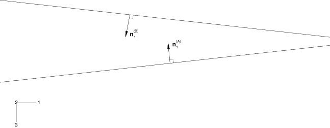
In its local coordinate system, the Truss part is oriented as shown in Figure 1.

From the main menu bar of the Property module, select to specify an approximate -vector for each truss structure. As noted earlier, the direction of this vector should be orthogonal to the plane of the truss. Thus, for truss B, the approximate = (−0.1118, 0.0, 0.9936); while for the other truss structure (truss A), the approximate = (−0.1118, 0.0, −0.9936).
You may want to check that your beam sections and orientations are correct. From the main menu bar, select and toggle on Render beam profiles to see a graphical representation of the beam profile. Toggle off Render beam profiles before continuing with the rest of the example. This functionality is also available in the Visualization module through the ODB Display Options dialog box.
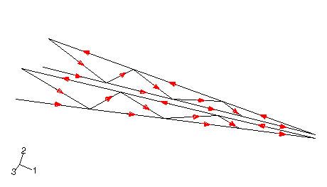
From the main menu bar, select to specify the beam tangent directions. Flip the tangent directions as necessary so that they appear as shown in Figure 2.

While both the cross bracing and the bracing within each truss structure have the same beam section geometry, they do not share the same orientation of the beam section axes. Since the square cross bracing members are subjected to primarily axial loading, their deformation is not sensitive to cross-section orientation; thus, we make some assumptions so that the orientation of the cross-bracing is somewhat easier to specify. All of the beam normals (-vectors) should lie approximately in the plane of the plan view of the cargo crane (see Figure 2). This plane is skewed slightly from the global 1–3 plane. A simple method for defining such an orientation is to provide an approximate -vector that is orthogonal to this plane. The vector should be nearly parallel to the global 2-direction. Therefore, specify = (0.0, 1.0, 0.0) for the cross bracing so that it is aligned with the part (and as we shall see later, global) y-axis.