Determining when to use a rigid body | ||
| ||
Figure 1 shows a rigid body. The shape of the rigid body is defined either as an analytical surface obtained by revolving or extruding a two-dimensional geometric profile or as a discrete rigid body obtained by meshing the body with nodes and elements. The shape of the rigid body does not change during a simulation but can undergo large rigid body motions. The mass and inertia of a discrete rigid body can be calculated based on the contributions from its elements, or they can be assigned directly.
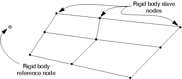
The motion of a rigid body can be prescribed by applying boundary conditions at the rigid body reference node. Loads on a rigid body are generated from concentrated loads applied to nodes and distributed loads applied to elements that are part of the rigid body or from loads applied to the rigid body reference node. Rigid bodies interact with the rest of the model through nodal connections to deformable elements and through contact with deformable elements.
The use of rigid bodies is illustrated in Contact.
It may be useful to make parts of a model rigid for verification purposes. For example, in complex models elements far away from the particular region of interest could be included as part of a rigid body, resulting in faster run times at the model development stage. When you are satisfied with the model, you can remove the rigid body definitions and incorporate an accurate deformable finite element representation throughout.
The principal advantage to representing portions of a model with rigid bodies rather than deformable finite elements is computational efficiency. Element-level calculations are not performed for elements that are part of a rigid body. Although some computational effort is required to update the motion of the nodes of the rigid body and to assemble concentrated and distributed loads, the motion of the rigid body is determined completely by a maximum of six degrees of freedom at the rigid body reference node.
In Abaqus/Explicit rigid bodies are particularly effective for modeling relatively stiff parts of a structure for which tracking stress waves and distributions is not important. Element stable time increment estimates in the stiff region can result in a very small global time increment. Since rigid bodies and elements that are part of a rigid body do not affect the global time increment, using a rigid body instead of a deformable finite element representation in a stiff region can result in a much larger global time increment, without significantly affecting the overall accuracy of the solution.
Rigid bodies defined with analytical rigid surfaces in Abaqus are slightly cheaper in terms of computational cost than discrete rigid bodies and may yield smoother results. In Abaqus/Explicit, for example, contact with analytical rigid surfaces tends to be less noisy than contact with discrete rigid bodies because analytical rigid surfaces can be smooth, whereas discrete rigid bodies are inherently faceted. However, the shapes that can be defined with analytical rigid surfaces are limited.