Smoothing contact surfaces in Abaqus/Standard | |||||||||||
|
| ||||||||||
ProductsAbaqus/StandardAbaqus/CAE
Smoothing of common curved surface geometries
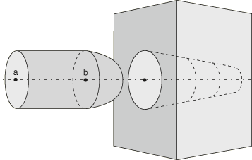
One method of surface smoothing applies to surface regions that are roughly axisymmetric, roughly spherical, or part of a toroidal surface. The smoothing method applies to general contact and surface-to-surface contact pairs. For example, the pin insertion model in Figure 1 could benefit from this smoothing: the body of the pin is cylindrical, the head of the pin is hemispherical, and the hole is conical. Surface-to-surface contact smoothing would also be effective if the surfaces were not perfectly axisymmetric, spherical, or toroidal; for example, if the pin body were slightly elliptical.

Effects of contact surface smoothing
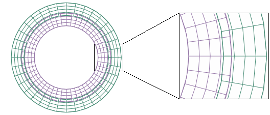
The impact of contact smoothing based on comparison of initial faceted surface geometry to initial idealized surface geometry can be demonstrated by a simple model. Figure 2 shows the initial mesh geometry for a two-dimensional model of concentric cylinders with an interference fit. The concentric cylinders are modeled with first-order elements of different sizes.

Discrepancies between the true surface geometry and the faceted surface geometry result in noise in the contact pressure solution if surface smoothing is not used. If the interference distance and resulting deformation distance is small with respect to the geometry discrepancy, this noise can have a significant effect on the accuracy of the solution. Although surface-to-surface contact typically handles these discrepancies better than node-to-surface contact, it is not unusual for the maximum deviation from the analytical pressure solution to be upward of 100%. The effects of the noise become less apparent for larger deformations, but they are never completely eliminated.
Applying smoothing of common curved surface geometries to general contact
Smoothing of common curved surface geometries for general contact is enabled by surface property assignments. Surface property assignments specify which surfaces are to be smoothed and the smoothing method to be used. The underlying geometry correction methods are the same for general contact and contact pairs:
-
The circumferential smoothing method is applicable to surfaces approximating a portion of a circle in two dimensions or a portion of a surface of revolution in three dimensions.
-
The spherical smoothing method is applicable to surfaces approximating a portion of a sphere in three dimensions.
-
The toroidal smoothing method is applicable to surfaces approximating a portion of a torus in three dimensions (i.e., a circular arc revolved about an axis).
For each surface, you must specify the appropriate geometry correction method and either the approximate axis of revolution (for circumferential or toroidal smoothing) or the approximate spherical center (for spherical smoothing). For toroidal smoothing, you must also specify the distance of the center of the circular arc from the axis of revolution, and the line joining point (Xa, Ya, Za) and the center of the circular arc should be perpendicular to the axis of revolution.
Input File Usage
Use the following option to apply a geometric correction and define the parameters by specifying coordinates:
SURFACE PROPERTY ASSIGNMENT, PROPERTY=GEOMETRIC CORRECTION, DEFINITION=COORDINATES
data lines to define smoothing regions
Several examples for data line entries are shown below. Repeat the data lines as many times as necessary to define the appropriate geometry corrections for all surfaces in the contact domain.
To apply circumferential smoothing to a surface with an axis of symmetry passing through points (Xa, Ya, Za) and (Xb, Yb, Zb):
surface, CIRCUMFERENTIAL, Xa, Ya, Za, Xb, Yb, ZbTo apply spherical smoothing to a surface with a spherical center at point (Xa, Ya, Za):
surface, SPHERICAL, Xa, Ya, Za To apply toroidal smoothing to a surface with an axis of symmetry passing through points (Xa, Ya, Za) and (Xb, Yb, Zb) with the center of the revolved circular arc at a distance R from the axis of symmetry:
surface, TOROIDAL, Xa, Ya, Za, Xb, Yb, Zb, RUse the following option to apply a geometric correction and define the parameters by specifying nodes:
SURFACE PROPERTY ASSIGNMENT, PROPERTY=GEOMETRIC CORRECTION, DEFINITION=NODES
data lines to define smoothing regions
Several examples for data line entries are shown below. Repeat the data lines as many times as necessary to define the appropriate geometry corrections for all surfaces in the contact domain.
To apply circumferential smoothing to a surface with an axis of symmetry passing through nodes a and b:
surface, CIRCUMFERENTIAL, node a, node bTo apply spherical smoothing to a surface with a spherical center at node a:
surface, SPHERICAL, node aTo apply toroidal smoothing to a surface with an axis of symmetry passing through nodes a and b with the center of the revolved circular arc at a distance R from the axis of symmetry:
surface, TOROIDAL, node a, node b, RAbaqus/CAE Usage
Contact surface smoothing can be applied only to native geometry models in Abaqus/CAE. By default, Abaqus/CAE automatically detects all circumferential, spherical, and toroidal surfaces in the general contact domain that can be smoothed and applies the appropriate smoothing.
Use the following option to prevent automatic surface smoothing of a model:
Interaction module: Create Interaction: General contact (Standard): Surface Properties: Surface smoothing assignments: Edit:
toggle off Automatically assign smoothing for geometric faces
Use the following option to manually apply smoothing to a surface:
Interaction module: Create Interaction: General contact (Standard): Surface Properties: Surface smoothing assignments: Edit:
Select surface, click the arrows to transfer surface to list of smoothing
assignments.
In the Smoothing Option column, select REVOLUTION to apply circumferential smoothing, select SPHERICAL to apply spherical smoothing, select TOROIDAL to apply toroidal smoothing, or select NONE to prevent smoothing of the surface.
Example: Pin-in-hole with general contact
To improve contact pressure accuracy for the model in Figure 1, contact smoothing can be applied to both the master and slave surfaces. Two different geometric correction methods are required for the pin (the slave surface), so additional surfaces are defined corresponding to regions of the slave surface. Spherical smoothing is defined for the tip of the pin. Since the body of the pin and the hole share an axis of revolution, circumferential smoothing is applied to both of these surfaces. This surface smoothing definition applies even if the cross-sectional shapes of the pin and hole deviate from perfect circles.
SURFACE INTERACTION, NAME=FRICTION1
CONTACT
CONTACT INCLUSIONS
PIN, HOLE
CONTACT PROPERTY ASSIGNMENT
 , , FRICTION1
SURFACE PROPERTY ASSIGNMENT, PROPERTY=GEOMETRIC CORRECTION, DEFINITION=COORDINATES
PIN_TIP, SPHERICAL, Xb, Yb, Zb
PIN_BODY, CIRCUMFERENTIAL, Xa, Ya, Za, Xb, Yb, Zb
HOLE, CIRCUMFERENTIAL, Xa, Ya, Za, Xb, Yb, Zb
Applying smoothing of common curved surface geometries to surface-to-surface contact pairs
Smoothing of common curved surface geometries for contact pairs that use a surface-to-surface contact formulation is enabled by creating a surface smoothing definition. A contact pair definition references this smoothing definition to apply geometric corrections in the contact formulation (the physical geometry of the model is not altered).
The surface smoothing definition lists all of the faceted regions in the contact pair surfaces that must be smoothed, as well as the geometry correction method that should be applied to each region. Three geometry correction methods can be employed:
-
The circumferential smoothing method is applicable to surfaces approximating a portion of a circle in two dimensions or a portion of a surface of revolution in three dimensions.
-
The spherical smoothing method is applicable to surfaces approximating a portion of a sphere in three dimensions.
-
The toroidal smoothing method is applicable to surfaces approximating a portion of a torus in three dimensions (i.e., a circular arc revolved about an axis).
Each surface-to-surface contact pair refers to a single smoothing definition; therefore, a smoothing definition must list all of the smoothed regions and applicable geometry correction methods for the contact pair. Geometry corrections can be applied to master surfaces and to slave surfaces; you can also apply corrections to selected regions of each surface. A surface smoothing definition can include multiple regions and different geometric correction methods for each region. For each region, you must specify the appropriate geometry correction method and either the approximate axis of revolution (for circumferential or toroidal smoothing) or the approximate spherical center (for spherical smoothing). For toroidal smoothing, you must also specify the distance of the center of the circular arc from the axis of revolution, and the line joining point (Xa, Ya, Za) and the center of the circular arc should be perpendicular to the axis of revolution.
Input File Usage
Use both of the following options to apply surface-to-surface contact smoothing:
CONTACT PAIR, GEOMETRIC CORRECTION=smoothing_name
SURFACE SMOOTHING, NAME=smoothing_name
data lines to define smoothing regions (see below)

Use the following data line to apply circumferential smoothing to
surface regions with an axis of symmetry passing through points
(Xa, Ya, Za) and (Xb, Yb, Zb):
slave_region, master_region, CIRCUMFERENTIAL, Xa, Ya, Za, Xb, Yb, Zb

Use the following data line to apply spherical smoothing to
surface regions with a spherical center at point (Xa, Ya, Za):
slave_region, master_region, SPHERICAL, Xa, Ya, Za

Use the following data line to apply toroidal smoothing to
surface regions with an axis of symmetry passing through points
(Xa, Ya, Za) and (Xb, Yb, Zb) with the center of the revolved circular arc
at a distance R from the axis of symmetry:
slave_region, master_region, TOROIDAL, Xa, Ya, Za, Xb, Yb, Zb, R

Repeat the data lines as many times as necessary  to define the appropriate geometry corrections for all surfaces in the contact pair.
Abaqus/CAE Usage
Abaqus/CAE can automatically identify any circumferential, spherical, or toroidal surfaces in a contact interaction that will benefit from contact smoothing and apply the necessary geometry correction methods.
Interaction module: contact interaction editor: Surface Smoothing: Automatically smooth 3D geometry surfaces when applicable
Surface-to-surface contact smoothing cannot be applied to surfaces on orphan mesh models.
Example: Pin-in-hole with contact pairs
To improve contact pressure accuracy for the model in Figure 1, contact smoothing can be applied to both the master and slave surfaces. Two different geometric correction methods are required for the pin (the slave surface), so additional surfaces are defined corresponding to regions of the slave surface. Spherical smoothing is defined for the tip of the pin. Since the body of the pin and the hole share an axis of revolution, circumferential smoothing is applied to both of these surfaces. This surface smoothing definition applies even if the cross-sectional shapes of the pin and hole deviate from perfect circles.
CONTACT PAIR, TYPE=SURFACE TO SURFACE, INTERACTION=FRICTION1,
   GEOMETRIC CORRECTION=SMOOTH1
PIN, HOLE
SURFACE INTERACTION, NAME=FRICTION1
SURFACE SMOOTHING, NAME=SMOOTH1
PIN_TIP, , SPHERICAL, Xb, Yb, Zb
PIN_BODY, HOLE, CIRCUMFERENTIAL, Xa, Ya, Za, Xb, Yb, Zb
![]()
Smoothing of faceted surfaces based on comparison to CAD representations
Simulations using general contact submitted from 3DEXPERIENCE platform Scenario Creation apps can use a technique to improve finite element representations of contact surfaces. This technique is based on deviations of the original element-based surface geometry from a more accurate reference representation of the undeformed geometry and leverages CAD surface representations available in the 3DEXPERIENCE platform in the computation of contact geometry corrections. This technique is not available in explicit dynamic steps.
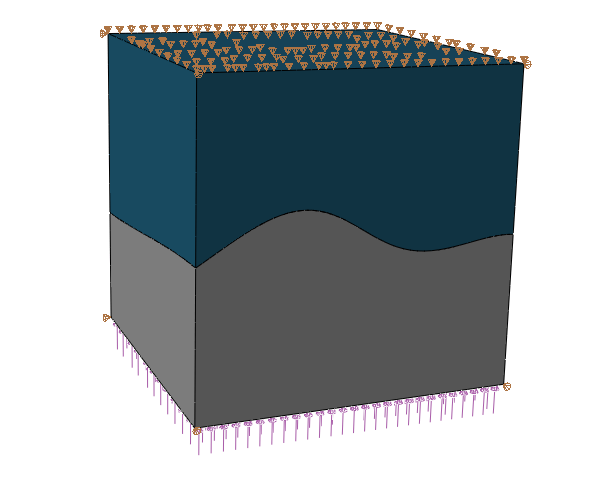
The CAD-based smoothing method is applicable to arbitrary surface shapes having CAD representations in the 3DEXPERIENCE platform. Consider the example shown in Figure 3. This example is constructed such that the analytical solution has a uniform, uniaxial stress state of 108 Pa. The curved contact interface has closed contact and sticking friction everywhere, and the same elastic material exists on both sides of the contact interface. The meshes used in this example are made of quadratic hexahedral and wedge elements. The meshes do not have matched nodes across the contact interface, which causes significant stress noise if the contact surfaces are not smoothed, especially for small strains where the level of element deformation is less than or equal to the distances associated with the mismatch of faceted surface representations across the interface.

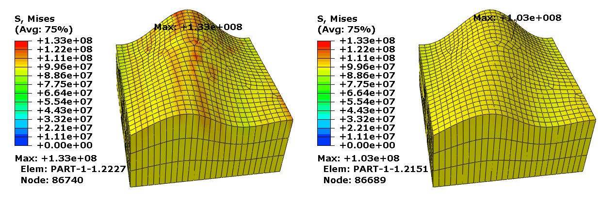
Figure 4 shows that CAD-enhanced contact reduces stress noise for this example. For example, the maximum Mises stress deviates from the analytical Mises stress solution by 33% without CAD-enhanced contact, and this deviation is less than 3% with CAD-enhanced contact. The CAD-based smoothing also significantly improves contact pressure results for this model.

![]()
Considerations for smoothing methods based on knowledge of idealized initial geometry
The smoothing methods in this section are used to adjust contact penetration/gap computations based on differences in undeformed geometries between faceted finite element surface representations and more idealized surface representations. The effects of the surface smoothing techniques discussed in this section tend to be most significant for analyses involving small deformation and coarse mesh discretization with first-order elements in the contact region; however, significant improvements to contact stress solutions are common even when the mesh is quite refined or higher-order elements are used. For analyses with large deformation these smoothing techniques typically have an insignificant effect on solutions. However, in some cases the smoothing can degrade the solution accuracy after large deformation; therefore, it is not recommended to use these smoothing techniques for large-deformation analyses. The effectiveness of the smoothing does not degrade upon relative motion between contact surfaces; for example, the smoothing technique works well for cases involving large sliding but small deformation.
The surface smoothing techniques discussed in this section assume that initial locations of surface nodes lie on the true initial surface geometry, with the exception of midside nodes of higher-order elements. These smoothing techniques remain effective even if the midside nodes of higher-order elements do not lie on the true initial geometry (models meshed using Abaqus/CAE always have midside nodes placed on the true initial geometry, but this may not be the case with other meshing preprocessors).