UJOINT | |||||||||
|
| ||||||||
ProductsAbaqus/StandardAbaqus/ExplicitAbaqus/CAE
Description
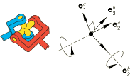
Connection type UJOINT imposes kinematic constraints and uses local orientation definitions equivalent to combining connection types JOIN and UNIVERSAL.
The connector constraint forces and moments reported as connector output depend strongly on the order of the nodes and location of the nodes in the connector (see Connector behavior). Since the kinematic constraints are enforced at node b (the second node of the connector element), the reported forces and moments are the constraint forces and moments applied at node b to enforce the UJOINT constraint. Thus, in most cases the connector output associated with a UJOINT connection is best interpreted when node b is located at the center of the device enforcing the constraint. This choice is essential when moment-based friction is modeled in the connector since the contact forces are derived from the connector forces and moments, as illustrated below. Proper enforcement of the kinematic constraints is independent of the order or location of the nodes.

Friction
Predefined Coulomb-like friction in the UJOINT connection relates the kinematic constraint forces and moments in the connector to friction moments about the unconstrained rotations (about the two directions of the connection cross). The UJOINT connection type consists of four hinge-like connections placed at the four ends of the connection cross (see Figure 1) that generate frictional moments about the cross axes. The frictional moments in each of these hinges are computed in a fashion similar to the HINGE connection.
The constraint forces and moments are used first to compute a reaction force, (the magnitude of the constraint forces enforcing the JOIN constraint), and a “twisting” constraint moment, (the magnitude of the constraint moment enforcing the UNIVERSAL connection), as follows:
The two cross directions are given by and . The constraint moment, , acts about an axis perpendicular to the connection cross given by . Both and are considered to be applied at the center of the connection cross. The constraint moment, , produces in each of the four hinges a bending-like moment about :
and a transverse force in the cross plane
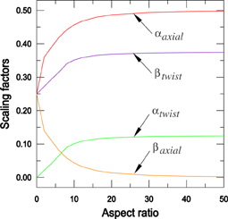
where represents a characteristic length of the cross arm between the center of the cross and the ends of the cross. The scaling factors and are nonlinear functions of the slenderness of the cross axes (the aspect ratio , where is the average radius of the four pins at the ends of the connection cross): they can be approximated by assuming the cross arm with rigid bodies for infinitely small aspect ratios, with Timoshenko beams for small aspect ratios (less than 20), and with Euler-Bernoulli beams for slender axes (large aspect ratios). Abaqus chooses the appropriate values automatically based on the user-specified geometric constants and . Figure 2 illustrates the evolution of the scaling factors as a function of the aspect ratio: as the aspect ratio approaches 0.0, approaches 0.0 and approaches 0.25; for large aspect ratios, approaches 0.125 and approaches 0.375.
The constraint force, , can be decomposed into axial forces along the two axes of the connection cross and a “bending” force perpendicular to the connection cross plane:
where
Friction in the UJOINT connection is the superposition of four HINGE-like frictional effects due to rotations about the two cross axes. Since the rotations about the local 1- and 3-directions are the only possible relative motions in the connection, the frictional effects (CSM1 and CSM3) are formally written in terms of moments generated by tangential tractions and moments generated by contact forces. In the following equations subscript 1 refers to frictional effects about the local 1-direction, and subscript 3 refers to frictional effects about the local 3-direction. The frictional effects are written as follows:
where the potentials and represent the moment magnitudes of the frictional tangential tractions in the connector in directions tangent to the cylindrical surface on which contact occurs, and are the friction-producing normal moments on the same cylindrical surface, and is the friction coefficient. Frictional stick occurs in a particular direction if or ; and sliding occurs if or , in which case the friction moments are and .
The normal moments and are the sums of magnitude measures of force-producing connector moments, and , and self-equilibrated internal contact moments (such as from a press-fit assembly), and , respectively:
The factor of two in the above equations comes from the fact that there are two hinges on each cross direction.
The moment magnitudes and are defined by summing the following contributions:
moment from axial forces, and , where , , and is an average effective friction arm associated with the constraint force in the axial direction in each of the pins (if is 0.0, and are ignored); and
moment from normal forces, and , where and are themselves sums of the following contributions:
transverse force contributions, (the magnitude of the total transverse force in the two hinges along the -direction) and (the magnitude of the total transverse force in the two hinges along the -direction):
where , is defined above, , and ; and
force contributions from “bending,” , obtained by scaling the total bending moment, (the magnitude of the total bending moment on each of the four hinges), by a length factor, as follows:
where , is defined above, and represents a characteristic overlapping length between the pins and their sleeves. If is 0.0, is ignored.
Thus,
The moment magnitudes of the frictional tangential tractions are and .
Summary
| ||||||||||||||||||||||||||